Monday, November 30, 2015

Switching to Adafruit BNO055

We managed to retrieve accelerometer and magnetometer data from IMU (LSM9DS0). But the raw data are not meaningful, so we tried to convert them to degree by ourselves. As the x, y values are unstable and the corresponding arctan changes all the time, which results in very unstable calculated degree. The expected deviation should be smaller than the inaccuracy, so this instability is unacceptable. We tried to calibrate it and have tried other methods found online but they didn't help.  


From Adafruit website, "If you've ever ordered and wire up a 9-DOF sensor, chances are you've also realized the challenge of turning the sensor data from an accelerometer, gyroscope and magnetometer into actual '3D space orientation'! Orientation is a hard problem to solve." The problem we met is exactly this one. After lots of trial and error, we decided to use Adafruit BNO055, which is a smart 9-DOF sensor that does the sensor fusion all on its own. So it will give absolute orientation as follows.


After testing, we managed to get meaningful data from BNO055. In the above figure on the left, the degree detected is 328 degree. When I turned the board to the right (in the figure on the right), the detected degree changed to 347 degree. Most important, when I don't move the board, the value keeps stable.

Monday, November 23, 2015

3-axis accelerometer/magnetometer IMU test

3-axis accelerometer/magnetometer IMU is connected with mbed using SPI and the sensor data is printed out.


Switching from hall effect sensor to reed switch to 3-axis accelerometer/magnetometer

We tested the hall effect sensor and attached it to 3pi robot. The robot works fine but the problem is that the size of sensor and magnet are both quite small while the magnetic field can only be detected when they are placed closely. This makes it very difficult as the robot cannot go straight along the line of magnets all the time. So we decided to try the reed switch as it is like a bar which might be helpful detecting more area. We changed the circuit we built on the robot and attached a reed switch.


I even tried to connect two reed switches in parallel to extend the area they can detect. But it didn't help too much. Because the primary problem is the robot will deviate eventually and the deviation accumulates as it goes. 


The robot system is now open loop and it is very hard to make it go straight by purely adjusting the speed of two motors as the actual behavior depends not only on the rotating speed of wheels but also the mass on the body. I tried to add some mass on the rear of the body to make the robot even. This helped a bit but trying to close the loop and adjust the behavior along the way should be the best solution. Therefore we picked a 3-axis accelerometer/magnetometer IMU and we'll connect it with mbed using SPI instead.


Saturday, November 21, 2015

Nov 21st

As the IR cameras are not available currently, we decide to use magnetic field to do our localization part. After testing hall effect sensors, we built a board and embedded magnets with different poles.


For the 3pi robot, we attached a hall effect sensor at the bottom of the chasis and built support circuits on the expansion board. Almost all hardware part for localization is done, after downloading the program to our robot, it's ready to go!


Thursday, November 19, 2015

mbed on 3pi

The mbed is now mounted on 3pi robot and it's able to control the two motors. The 3pi robot with mbed can now moving zigzag by programming mbed.

Tuesday, November 17, 2015

Hacking Wii IR Camera Sensor

This week we  begin our work on Wii IR camera sensor.  We first order Wii remote and then hack the Wii IR sensor by ourselves.

Wii IR remote
I then disassembly it using screw driver and get the IR sensor chip - GH2702-H5.
I  also get them wired and the chip is shown as below.
Hacking the IR Camera Sensor

IR camera sensor
We are going to test the IR camera sensor later. Stay tuned.


Moving on to m3pi

It's time to mount mbed onto 3pi robot. We ordered expansion kits and soldered corresponding components on the expansion PCB. After assembly, it's connected to the 3pi robot. The next step is to insert mbed and use mbed to control the robot instead of the original ATmega328p microcontroller.


3pi robot

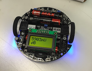
We use Pololu 3pi robots to execute area covering tasks. After inserting batteries, the robot looks like this.


After consulting the 3pi user guide online, I managed to control the two DC motors and set speed accordingly. At the time being, I haven't mount mbed on it, so I used the external AVR ISP programmer to program the microcontroller included in the robot (ATmega328p).


The robot is now able to move zigzag, which is the desired behavior we'll use to cover an area. It's realized by setting appropriate speed of two motors.

System Diagram


This is a simple system diagram showing the components we'll use in our system and how they interact with each other.

Our Project

Group members: Yiling Qiang, Ao Sun

Motivation

Area covering is an important task for mobile robots, with many real-world applications such as floor-cleaning, de-mining, and harvesting. In recent years, there is growing interest in the use of multiple robots in coverage, motivated by efficiency and robustness.

Goals

Build a multi-robot system with at least three coordinated robots to solve the area covering problem.
- When one of the slave robots is out of charge, it moves to a certain area. Another fully-charged robot will go to where it stopped and continues its job to cover the remaining area.
- Master node coordinates which slave is working and which slave is waiting.
- Slave robots communicate with master and act according to the information they receive from master.